The 100 horsepower 80 pound Stirling engine for a reasonable price???
More Thoughts on Stirlings and ICEs

Home built drawing of Solar Miller Layout Stirling engine

Solar-Miller (tm) configuration of Stirling engine.  The regenerators (inside between displacer and crankshaft) and  radiator ( on top of the two displacers drawn in red) have been removed for clarity.
Support this project  directly at paypal.me/CleanStirling

A 100 horsepower Stirling engine has heretofore been unheard of.  Stirlings have either been huge behemoths or low powered specialty engines that costs a small fortune.  Some commercial models cost over $150,000.   Justifying such a price is a tall order that the Stirling design has met.  Now, with advent of the Solar-Miller (tm) configuration the same advantages that justify the high price are becoming available to lower margin applications and even enthusiasts, because the price is dropping and the power density is comparable.  Any application, from converting waste heat into usable electricity to wind powered refrigeration is now economically viable.

Tweet
Note how all moving parts are enclosed and protected from dust, dirt, combustion products, heat, mold and mildew.
Certain details that allow this design to function have been withheld
The most efficient working fluid is hydrogen gas.  Most any gas will work.  Avoid using air with oxygen, because it combines with the lubricants and then burns explosively. 
Note also, how this engine was designed as a pressure vessel to work at high power densities.
Contribute to funding the building of this engine paypal.me/CleanStirling

Background


If you are unfamiliar with the Stirling engine, use your search engine and you will discover that the Stirling engine is a very promising technology that has never lived up to its potential because of the high costs to manufacture, the low power output, and the unresponsiveness of the engines.  This design solves the power density and costs issues.


These engines prefer to run at one continuous speed which is only moderately influenced by fuel input.  Do not expect to "rev" your Stirling engine.  Consequently, do not attempt to utilize a Stirling engine where there is the need for sudden acceleration, such as in non hybrid cars or aircraft.  You don't want to be flying your homebuilt airplane, stall, and then expect the Stirling engine to save you.  The response is simply too slow.   Non hybrid aircraft propulsion is the best example of the wrong application for this engine.  Instead, choose the right application and you will love the economy and quiet operation that are the hallmark of the Stirling.


Imagine an engine that runs without the noise of fuel exploding out of the exhaust valves, instead, the fuel is burned quietly similar to a gas log fireplace or your water heater.  No complex plumbing of either fuel or air supply is needed.  The air and fuel follow simple plumbing to the area where the heat is needed, they combine continuously, efficiently, completely, cleanly and the exhaust gases are then plumbed away.  No complex ignition system or timing circuits are required.   With the Stirling's continuous flow,  air and fuel valves don't open and close every time the piston completes a stroke.  Instead of controlling air, fuel, and pressurization each stroke of the piston, the Stirling controls the heat energy of the fuel after the fuel and air are combined.  Moving the working gas inside from the heating area to the cooling area is much simpler and more efficient than creating heat exactly where and when it is needed for each stroke of the piston and then wasting most of it out the exhaust ports.  This is the most difficult part of Stirling operation to grasp;  Air can be heated and cooled (causing expansion and contraction) over 1500 times a minute.  Search u tube.com for videos that prove that this is true and that these engines actually work.  Once you grasp this concept, the Stirling's simplicity will enchant the engineer in you.


The internal combustion engine has, until now, overshadowed the Stirling engine in performance with the ability to process chemical energy into motion at a much higher rate and in a more compact form.  A four cylinder gasoline powered internal combustion engine can convert a gallon of gas into work in under 15 minutes.  The Stirling engine has always had a bottleneck in the energy input that prevented compact high volume throughput of energy.  This design directly addresses that bottleneck as well as some of the complexities that made the Stirling engine expensive to produce.
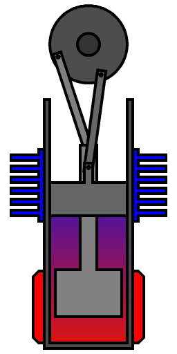
Traditional Stirling layout
A traditional design for reference.

compare to the internal combustion engine.

internal combustion engine pic
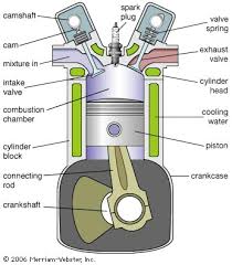
Fewer parts finaly means lower costs, (just as soon as we get the volume )

Parts that the Stirling engine doesn't need:

seperate starter, (utilizes the alternator),
fuel injection system (burns like a Coleman (R) stove),
complex ignition system (just one piezo electric spark to start the heat source),
high pressure fuel pump,
turbo charger,
valves,
timing belt,
camshaft,
rocker arms,
oil pump,
oil filter,
oil pressure monitor,
check engine light,
intake manifold,
exhaust manifold,
catalytic converter ( catalyst used in combustion area),
EGR valve,
oxygen sensor,
muffler

Maintenance that the Stirling doesn't need:

Oil changes,
spark plug changes,
timing belts, valve adjustments, 
ignition wires,
oxygen sensor,
check engine light


Applications


Stirling engines run on any heat source, from geothermal to solar to propane to wood.  Anything that produces heat can potentially power this engine.  Consequently, if you have waste heat, why not use it to power your lights and heat your water?


Stirling engines are quiet and reliable.  If you need a portable generator for a mobile home, off the grid homes and offices or trade shows, consider the Stirling.  The cooling cycle of the engine can be plumbed to provide you with hot water.


Running a Stirling engine in reverse, causes it to pump heat from the hot side to the cold side.  This is how commercial cryocoolers work to convert air into a liquid.  This design can be used as a heat pump, either cooling or heating fluids as desired.  If you have need of refrigeration and don't have electricity, this design can be adapted to produce power from fuel on one side and heat pumping on the other.  If you have a noise issue with conventional refrigeration, or want to use non polluting refrigerant gases , this might be the ticket.


Just as important as when Stirling engines make sense is recognizing when they don't.  Stirlings are only moderately responsive to fuel input.  Do not use this engine where responsiveness is an issue.
Sign of the times - Alternative Fuel

Possible engine fuel source
Man starting a fire
"...it was a pit fire with poop. The pot doesn't smell like poop, it smells like a mesquite fire because the cows like to eat the mesquite beans from the trees."
(http://www.craftster.org/forum
/index.php?topic=318202.0)

History


The Stirling engine has been around in various forms since 1817 when Robert Stirling patented his first design.  Even earlier variations of this device are speculated to have been employed to  move massive doors in Roman temples over 2000 years ago.  Current designs are found in cryocooling, home energy generation, solar power generation, submarine propulsion, and space craft power generation.  Attempts to utilize the Stirling engine in automobiles were unsuccessful.  This may have been due to a tendency to treat the Stirling engine as a poor substitute for the internal combustion engine.  A more appropriate alternative is to treat the Stirling engine  as a unique power source; certainly, its distinctive characteristics recommend it to a variety of applications entirely outside the realm of the internal combustion engine.  Just as the electric motor and the turbine are each uniquely suited for certain tasks, so too is the sterling engine.  Two variables have heretofore inhibited the widespread adoption of the Stirling engine - cost and power density.  Lower  manufacturing costs and increased power output, give the Solar-Miller (tm) Stirling engine a  competitive edge over all previous applications.. 
Reverent Robert Stirling

 Robert Stirling

A quick word on maintenance and repair.  little.  That is right, these engines are sealed at the factory, you can't open them beyond re-pressurizing the working gas.  The bearings are located away from the heat source and have very little stress on them.  The output shaft seal, if you are using a sealed one can be changed without accessing the inside of the engine.  If you manage to break the output shaft, or drop something on the case that bends it, or drill a hole into it, well, they don't cost that much.  On the other hand, if you recover the engine after it has been submerged in water, simply hose it off and you are good to go.

And they are designed to be recycled.


Big talk, but how?

Simply eliminate the bottleneck to power input and the extra parts.  The Stirling engine was designed in 1817 with two pistons, which requires multiple seals and actuators while limiting the surface area which can transmit heat to the working fluid. 

This design rotates the displacer instead of reciprocating it.  

Suddenly there is no more limit on the surface area for heat energy transfer, no springs, no internal seals, no separate actuators, no reason not to power both sides of the power piston, no exposed external moving parts and only one external seal on the output shaft which can itself be sealed with an internal alternator.
Original concept by Robert Stirling


Solar Miller Layout

Heat transfer area is in red


Drawing of home built version Solar Miller Stirling engine layoutThe displacers are in red.  The heat transfer area is the entire length of the displacers.

Conclusion

A simple redesign has eliminated most of the problems of a Stirling engine.  Power output can be formally addressed at each step of the power conversion process and the layout easily customized to the job.  Stirling engines convert heat into mechanical motion.  This design allows the heat exchanger to be optimized for the heat source and the stroke adjusted to achieve the desired torque.  Applications in which even power output and high efficiency, such as the hybrid automobile and electricity generation, are ideal for the Stirling engine as well as new applications like distillation and refrigeration.  The internal combustion engine, the electric motor and the turbine all have their market niches.  And now the Stirling is ready for a larger role

Exploded view


Exploded view

Contact

We are currently seeking a manufacturing partner.  In the meantime, we can license this design for your application.  We can assist in scaling this design to your application.  If you pay in advance, we can hand build one for you.   Manufactures are welcome to license this design on a per unit basis.   Hobbyists are welcome to produce non commercial models for personal enjoyment without charge but are advised that pressure vessels are dangerous to work with, be safe and understand that we assume no liability for your use of our designs.  The most avoidable accident with pressurizing Stirling engines is do not use compressed air with oxygen in it as the lubricants tend to blow up.  

fractalogic @ gmail. com (omit the spaces)
Hobbyists, drop us a note to show how you are doing.  More detailed plans are available for a nominal fee.

fractalogic @ gmail. com  (omit spaces)


Copyright (c) 2011
If you want a working model of the Excel (r) spreadsheet depicted below, send a $10.00 donation through PayPal to fractalogic @ gmail. com (omit the spaces) and request Stirling Output Predictor spreadsheet, by return e-mail (include your e-mail, we don't spam or sell them)
Here is the Excel Spreadsheet EXCEL SPREADSHEET TO CALCULATE STIRLING ENGINE OUTPUT
Indigogo

Estimate or calculate the output of your engine


Predict in horsepower, the power output of a Solar-Miller (tm) Style Stirling Engine        
Change the green boxes to achieve the desired output    


    Case 1 2 3        
Horsepower Predicted     1.1 16.7 40.1 hp      
                   
                   
Fill Pressure PSI     0 200 500 psi      
    ATM 1 14.60919276 35.0229819        
    Fahrenheit     Kelvin        
Temperature Fill Temp. 80 f   299.8        
  Low 100 f   310.9        
  low average   316.7   431.3        
  high average   533.3   551.7        
  High 750 f   672.0        
      Carnot 54%          
                   
                   
Displacer       inch          
  Diameter     5          
  Heat exchanger length     25          
  Displacer length     25          
                   
  Volume   490.87 Cubic inch 8.04 liter      
  Swept Volume   156.25 Cubic inch 2.56 liter      
  Dead space   20 Cubic inch 0.33 liter      
                   
Piston Diameter   6   Area 28.3 sq in    
  stroke   4            
  Cylinder length   14            
  Volume @ TDC 176.3 Cubic inch 2.89 liter      
  @ 1/2 way 232.8 Cubic inch 3.81 liter      
  @ BDC 289.3 Cubic inch 4.74 liter      
                   
Calculations   1 2 3          
V=nRT/P   156.3 156.3 156.3          
                   
      Piston Position   Pressure Delta        
P=nRT/V cold   TDC 13.028 190.333 456.291 psi    
      CDC 9.864 144.100 345.454 psi    
      BDC 7.936 115.938 277.940 psi    
T=PV/nR                  
temp drop from moving piston                  
What temp alone would do this     TDC 149.08 149.08 149.08      
      CDC 344.39 344.39 344.39      
      BDC 539.70 539.70 539.70      
      Difference 390.63 390.63 390.63      
pressure differential on piston                  
cold     Delta other side of piston     (Mechanically equalized Miller cycle)      
P=nRT/V fill pressure 1     fill pressure 2   Fill pressure 3      
cycle PSI Delta PSI   PSI Delta PSI PSI Delta PSI    
Heat TDC 18.7 4.1   273.8 60.5 656.4 145.0    
Heat CDC 22.1 11.9   323.0 173.6 774.3 416.1    
Heat BDC 14.6 -4.1   213.3 -60.5 511.4 -145.0    
Cool CDC 10.2 -11.9   149.4 -173.6 358.3 -416.1    
                   
Pressure on piston   Area 28.3 Sq In       SI  
    PSI 11.9 P/SI 173.6   416.1 P/SI  
      336   4907   11764 Lbs  
    psi in foot/lbs for 1/6 of rotation              
(Lbs*S/12)/6   Torque 18.7   272.6   653.6 ft/lbs/rotation  
Torque*RPM   RPM 1500.0            
    HP 5.3   77.9   186.7    
    Efficiency 21% = mech x heat trans x Carnot    
mechanical efficiency     WAG 50% 80% 54%    
        Wild As Guess   (Th-Tc)/Th      
    Yield 1.1 HP 16.7 HP 40.1 HP  


Conversion units                  
                   
Mole n=PV/RT   0.10407 1.520408 3.644911698        
                   
1 HP = 33000 ft/lbs/min     33000            
1 mole= 24.47 liter at 25 deg C (298K)                  
                   
R constant     0.08206            
1 cubic inches =     0.01639 liter          
1 linear inch=     2.54 cm          
PSI/ATM     14.696 14.69595          
ATM/PSI     0.0680            
HP Constant     5252            


We use this spreadsheet to help us design the power output.  As we experiment, it gets more and more complex.
Last Updated on 4/25/2011
By fractalogic @ gmail.com